The basics of sound generation
Small changes in air pressure, which are superimposed on the static air pressure, generate sound. It propagates in waves in the medium air at a constant speed of sound C of approx. 340 m/s. The human sense of hearing can perceive airborne sound in the frequency range from approx. 16 Hz to approx. 20 Khz. In nature, sound is generated by movement. This can happen through one-off events, e.g. thunder caused by lightning, or continuous events, e.g. water splashing, rain pattering or the rustling of leaves. Other examples of naturally generated sound are animal sounds, voices or instruments.
Sound events are divided into the following groups: Tones, sounds, noises, bangs.
Sound generation through electro-acoustic transducers
To reproduce speech or music, it is necessary to convert an electrical signal into an acoustic signal. For this purpose, air pressure fluctuations are generated by means of a driven membrane. Various electro-acoustic transducer principles are used for this purpose. The most widespread is the principle of the electrodynamic loudspeaker, in which the force for driving the diaphragm is generated by a conductor through which the signal current flows in a magnetic field.
The classic electrodynamic loudspeaker works according to the moving coil principle. This principle is the basis of the usual cone and dome loudspeakers and is based on the fact that the so-called Lorentz force F acts on a current-carrying conductor wound into a coil (voice coil) in a ring-shaped magnetic field B. The magnetic field is usually generated by a ferromagnetic field. The magnetic field is usually generated by a ferrite or neodymium magnet.
The diaphragm is firmly connected to the voice coil and can move in an axial direction. It is guided by a beaded edge and centering spider. When force is applied to the voice coil wire, the diaphragm displaces the air in front of it.
When an alternating current flows through the voice coil, the diaphragm generates an alternating pressure by compressing and rarefying the air, which the ear perceives as sound.
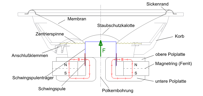
The picture shows a cone loudspeaker with its components in section. This type of loudspeaker gets its name from the cone-shaped membrane, which is made of paper, plastic, light metal or composite materials.
Due to the frequency-dependent coupling of the cone movement to the air, relatively large volumes of air have to be displaced to reproduce low frequencies. This is why woofers are transducers with large diaphragm surfaces and suspensions that allow a large diaphragm excursion.
As the frequency increases (decreasing wavelength), the diaphragms can become smaller. For this reason, small moving coil loudspeakers with dome or ring diaphragms are often used to reproduce the high frequency range. The diaphragm diameters of such tweeters are in the range of 15 mm to 40 mm.
As already mentioned, the reproduction of the low-frequency range tends to require large diaphragms, while the reproduction of the high-frequency range tends to require small diaphragm surfaces. Normally, these conflicting requirements cannot be combined in one loudspeaker, so that a system with at least two transducers is required for broadband transmission of the audio frequency range.
Sound propagation: speed of sound, frequency, amplitude, wavelength
Mechanical vibrations from a sound source cause periodic compression and rarefaction of the air particles in the surrounding air. This pressure fluctuation propagates as a longitudinal wave. The air molecules move around a rest position. In the carrier medium, the pressure wave propagates at a characteristic, constant propagation speed (speed of sound). In air, the speed of sound is C = approx. 340 m/s.
The frequency of the sound wave indicates the number of oscillations per second. One oscillation means that the air molecule goes through the movement cycle once (resting position-maximum-minimum-resting position). The unit of frequency f is Hertz (Hz).
The amplitude A denotes the maximum value of the particle deflection.
Each frequency f has a wavelength λ, which is given by the following relationship between the speed of sound and frequency:
λ = C/f
The wavelength λ indicates the distance between two neighboring particles that have the same oscillation state (same deflection and same direction of movement)
Low frequencies have long wavelengths, high frequencies have short wavelengths.
Examples of wavelengths for airborne sound:
– 100 Hz: wavelength approx. 3.40 m
– 1000 Hz: wavelength approx. 34.0 cm
– 10000 Hz: wavelength approx. 3.40 cm
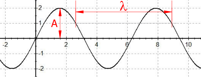
Amplitude A, wavelength λ
Almost all acoustic effects are frequency-dependent and therefore also wavelength-dependent. To understand the effects of sound radiation, it is helpful to think in terms of wavelength.
Interference, reflection, diffraction
From a point sound source that radiates undisturbed through objects or boundary surfaces in a free field, the sound wave propagates in a spherical shape. If this is not the case, the spherical propagation is disturbed by wavelength-dependent effects of interference, reflection and diffraction. The minimum dimensions of a real sound source alone allow these effects to occur.
Interference occurs when two sound waves of the same frequency overlap. In the case of a loudspeaker membrane, this is already given by the dimensions themselves. The sound is produced by many points on the diaphragm, which leads to interference, especially at an angle.
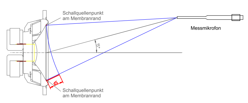
Principle representation of the path difference dS, of two sound sources imagined at the edges of the membrane.
If dS= (2n+1)*λ/2 the sound components cancel each other out, if dS= n*λ the components add up
Reflection occurs when a sound wave hits an obstacle that is large in relation to the wavelength and is reflected there according to the laws of reflection angle of incidence = angle of reflection. Reflection phenomena are divided into early reflections, reverberation and echo depending on the time of arrival at the ear after the direct sound. The human ear only perceives an echo as a separate delayed sound event from delay times of > 0.1 s. This requires a distance of the reflecting surface of more than 17 m (corresponding to a sound path of 34 m). Echo is not to be expected in normal-sized listening rooms.
In listening rooms, reflections from the room’s reflecting surfaces appear in the form of early reflections and reverberation that are not perceived separately from the direct sound component. They increase the volume perceived by the listener and create a spatial representation.
But reflection effects can also be found on small surfaces, e.g. the baffle of a loudspeaker cabinet. Higher frequencies (shorter wavelengths) are reflected at the front of the enclosure, resulting in hemispherical radiation. Low frequencies (long wavelengths) are emitted in a spherical shape (the sound is diffracted around the enclosure). (see also 2.3 Radiation behavior of loudspeakers)
Diffraction occurs when the sound wave, which propagates spherically from the source, encounters an obstacle. Diffraction effects (also known as diffraction) occur when the size of the obstacle is of the same order of magnitude as the wavelength. If the wavelength is significantly greater, the sound is diffracted around the relatively small obstacle with almost no effect on propagation. If the wavelength is significantly smaller than the obstacle, mainly reflection takes place and diffraction effects only occur at the edges of the obstacle. Wavelengths of audible sound are in the range from 1.7 cm (20 Khz) to 21 m (16 Hz). It is important to consider this order of magnitude if you want to clarify which sound components are diffracted around obstacles or reflected by them due to their wavelength.
Radiation behavior of loudspeaker boxes
The extent to which sound is radiated directionally depends on the size of the sound source, the baffle geometry or sound guide geometry and, to a large extent, the wavelength. If the sound source and/or the baffle is small compared to the wavelength, the sound wave is diffracted around the source and largely spherical radiation takes place for these frequencies. Higher frequencies are influenced by reflection, diffraction and interference effects in such a way that directional radiation occurs. This means that a loudspeaker box produces a more or less evenly decreasing sound pressure towards higher frequencies at an angle.
 Sound pressure frequency responses of a 2-way speaker with 17 cm bass-midrange loudspeaker
and 25 mm tweeter ring radiator in the horizontal plane at angles of 0°, 15°.
With commonly constructed loudspeakers (here 2-way loudspeakers with TT at the bottom and HT at the top), the behavior under angle is symmetrical to the right/left in the horizontal plane. In the vertical, however, it is different than in the horizontal and also asymmetrical up/down.
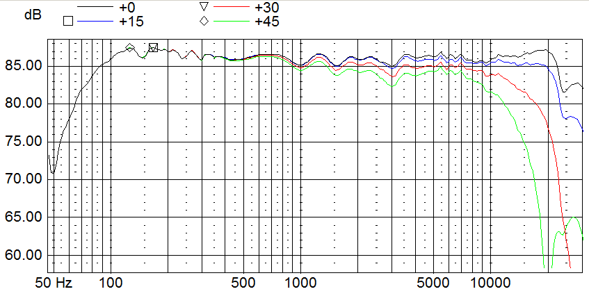
 Sound pressure frequency responses of a 2-way speaker with 17 cm bass-midrange loudspeaker
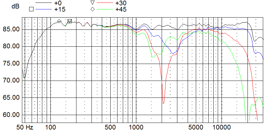
and 25 mm tweeter ring radiator in the vertical plane at angles of 0°, 15°, 30° and 45° downwards
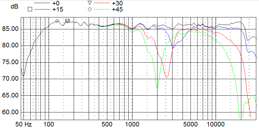
Sound pressure frequency responses of a 2-way speaker with 17 cm bass-midrange loudspeaker
and 25 mm tweeter ring radiator in the vertical plane at angles of 0°, 15°, 30° and 45° upwards
This sound pressure behavior at an angle is typical for commonly constructed loudspeakers (woofer, midrange driver and tweeter arranged vertically one above the other). It is quite good horizontally, but very unbalanced vertically.
This is caused by interference due to the distance between the woofer and tweeter. In the crossover range (in which both drivers emit the same frequencies), path differences occur at an angle (referred to as dS in the following diagram), which lead to sound cancellation
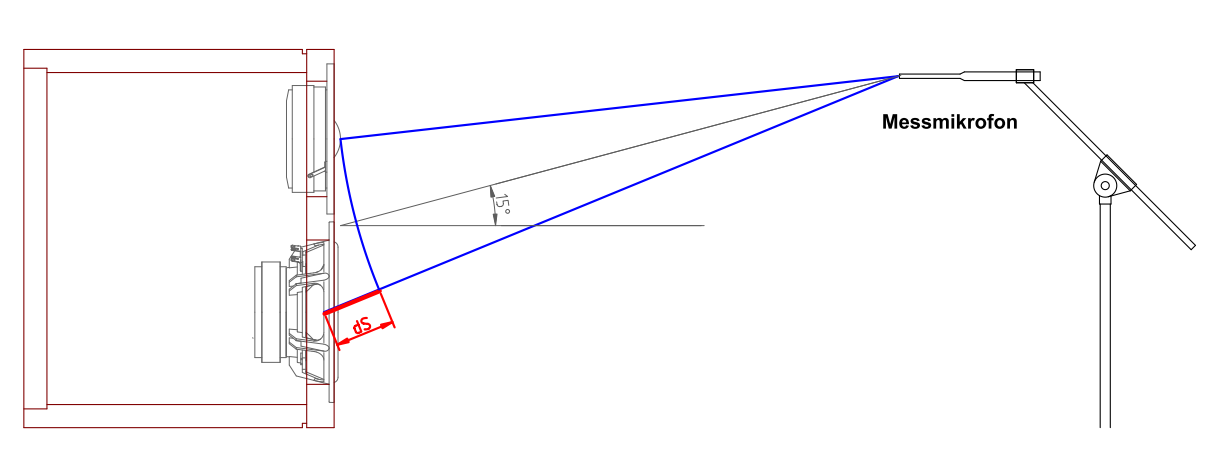
Difference in sound path (difference in aisle) of low-mid and high-frequency loudspeakers
for a typical 2-way speaker. Path difference dS at a vertical listening angle of 15° upwards
The size of the speakers (diameter), the distances between the speakers, the use of several speakers (e.g. in symmetrical arrangements), the number of paths, the choice of crossover frequencies and the filter slopes allow a wide range of dispersion characteristics to be set.
Direct and indirect sound: direct sound field, diffuse sound field
If a loudspeaker is not operated in a free field but in a room (which is usually the case), not only the sound components that the loudspeaker itself emits directly (direct sound) reach the listener, but also the sound components that find their way to the ear as reflected components of the room-bounding wall surfaces. This sound is referred to as indirect sound or reverberation and forms the so-called diffuse sound field. The term reverberation radius is also used in this context. The reverberation radius is the distance from the sound source at which the sound pressure levels of the direct sound field and the diffuse sound field are equal. Within the reverberation radius, the direct sound component predominates, outside the diffuse sound component. In highly absorbent rooms, the reverberation radius is large; in this case, the direct sound component determines the sound impression much more than in reverberant rooms.
In the free field, the level in the sound field decreases steadily with distance. The following applies to spherical radiation: doubling the listening distance means a 6 dB decrease in level. This is not the case in rooms or with highly directional radiation. There are many effects that determine the level at the listening position. The diffuse sound component, which has a significant influence on this, is very much dependent on the omnidirectional behavior of the loudspeaker (the sound pressure behavior of the loudspeaker at vertical and horizontal angles) and the absorption behavior of the wall surfaces in the listening room.
Imagine a loudspeaker that has a very linear sound pressure behavior on axis (0°) and a very evenly decreasing behavior at an angle. If this loudspeaker is now operated in a room that has a very inhomogeneous absorption behavior (e.g. strongly absorbing in the treble range and almost non-absorbing in the mid-range), the diffuse sound will ensure that we have a strongly centered sound impression.
The even absorption of the room over all frequencies in conjunction with loudspeakers that have a homogeneous omnidirectional radiation pattern is a necessary prerequisite for a balanced listening impression. Equal attention must be paid to both in planning and implementation!
Reverberation, reverberation time
If a room is filled with sound from a loudspeaker, the direct sound component reaches the listening point first. However, the direct sound also hits the surfaces surrounding the room, is reflected there and then reaches the listening point as an early reflection. Each reflection then forms a new sound source in the room, so to speak, delayed in time and with a reduced level, whose sound is in turn reflected by the other room surfaces and forms new sound sources. The number of reflections increases exponentially very quickly and forms the reverberant or diffuse sound field.
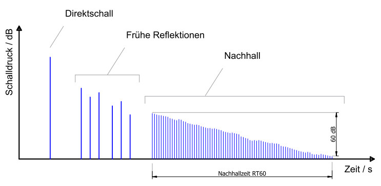
Time course of the sound field in a room after the impact of a single sound event (e.g. clapping or banging).
The diffuse sound field decays again within a certain time after the end of the sound irradiation. The time in which the diffuse sound level has dropped by 60dB is referred to as the reverberation time RT60 (RT stands for reverberation time).
Reverberation times of rooms are usually represented in octave or one-third octave frequency bands over the audible range and are best determined by measurements with an acoustic measurement system.
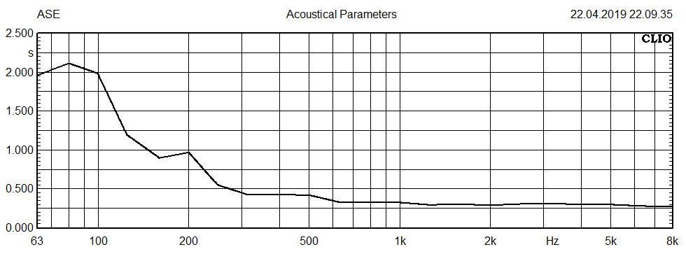
Example of a reverberation time measurement with the CLIO measuring system in an acoustically
largely optimized room before installation of bass and fundamental sound absorbers
The reverberation time of a room can also be determined approximately by calculation. The Sabine or Eyring formulas are used for this.


